Thursday, December 15, 2011

DZ123 in an older Life Like E8

This is another of the installations I had on the old web site which first appeared in December of 2003.  The engine used in this example was an E8A but this method would also apply to many of the older Life Like cab diesels that had a plastic frame and 2 weights over the axles.  The DZ123 decoder shown in this post is no longer made but any of today's small decoders would work very well. 

After removing the locomotive shell and rear weight, remove enough of the top of the rear weight the entire length for the decoder to fit in. There should be a ridge left on each side. This metal is not really hard and I do this with a hand file in about 15 minutes.
Next, file a slot up at an angle from the bottom front corner to the top at about 1/2 inch from the front. Then file a slot across the top to connect the angled
slot with the area removed for the decoder. Do this on both sides. This will be the channels for the wires.
There are long wheel contact wipers that run the length of the plastic frame. You will need to remove all the existing connections to these.

Be very careful not to use too hot of a soldering iron. I recommend the use of locking tweezers to act as a heat sink on the motor contact lugs.
The decoder and wires can be secured in place using a small amount of Wathers Goo.

The black, blue, & gray wires go to the left and the red, orange, & white wires go to the right. Re-install the rear weight and plastic retaining clip.
Connect the orange wire to the top motor contact and the gray wire to the bottom. Use a small piece of .010 styrene to insulate the contact strip from the motor connection.
 
Solder the red wire to the right contact strip and the black wire to the left contact strip.


The white and blue wires get run all the way to the front up under the front weight and up the slots to be connected to the light.  In this example I had used the original light bulb but an LED could also be used with a resistor placed in series.
 
After checking all of the wires are clear of moving parts and that the flywheels are turning freely, the mechanism is ready to test run.


Thursday, November 3, 2011

TCS Z2 in an Atlas GP40


The older version of the Atlas GP40 did not have any provision for a board type decoder.  The sure fire way to get a wired decoder into one of these is get the frame milled by Aztec Manufacturing.  I've done many of those and they work out fine but this time I wanted to do something different.


Here is a look at the stock GP40 mechanism.  Notice that the two LED boards are put in differently.  They are actually different boards.  There is room under the rear LED board for a small decoder such as the TCS Z2 if the LED itself was not in the way.


These are the modifications I made to the right frame half.  I found that without the slot for the wires on the top of the frame, the shell was not resting square on the frame.


This photo shows a side by side comparison of the original rear board and the one I made from a shorter board from another Atlas engine. The SMD LED is wired to the board with magnet wire and hangs over the end of the board. It is now clear to leave enough room for the decoder and sticks out no more than the original board did.


Both circuit traces to the frame contacts are cut so that this is isolated from the frame.  The yellow and blue wires will get soldered to the LED and resistor on this board.  On this board rather than drill a hole I made the existing opening longer so all the decoder wires could go through the opening.


The Z2 decoder wires are cut to the following lengths:

Gray = 2"
Orange = 1-1/2"
Yellow & Blue = 7/8"
Red, Black, & White = 2-3/4"


On the front LED board a hole needs to be drilled at the location shown in this photo.  The black and white wires are connected as shown.

The circuit trace gets cut the the same
location as is commonly done.  The red wire goes through the hole and is soldered at the point shown in this photo.  With this board being component side up this will place the red wire on the right side of the locomotive.

As I do with many installations I have filed a groove into the right side of the motor to contain the gray motor wire and secure it with a tiny amount of Walthers Goo.


Here is the completed assembly before re-installing the shell.  The wires will lay in the groove and can be secured with scotch tape. 


I found that the best way to get the shell back on was to follow the steps that are in this photo.  The important thing is that the shell is seated properly on the frame so that the body mounted couplers are at the correct height.

Sunday, October 16, 2011

TCS M1 in an Atlas SD50

The engine that I happen to be using in this post is an SD50 but the mechanism is the same for the SD60 and SD60M.  Besides the TCS M1 decoder used here, any similar sized decoder would also work.


Today's small DCC decoders as well as the design of this popular model make it possible to easily install a wired decoder a less expensive alternate to the board type decoders that are made for these models.  No frame modifications are needed.


After dis-assembling the loco mechanism, make the modifications shown in this photo.  The hole is on the long hood end of the PC board which has the longer wide area.  Wire thickness may be different for each manufacturer of decoder so size hole for the decoder you are using.

Bright white LED's were added on later releases of these models and the PC boards were re-designed.  There is an extra part on these boards labeled C1 that will not be needed in a DCC engine and this should be removed.  If you have one of the older versions with the yellow LED's and want to replace them with bright white LED's now is the time to do it.

Guide all of the decoders wires through the hole from the bottom of the board.  Attach the decoder to the bottom of the board with Walthers Goo.


Stretch out each decoder to the point that they will be attached to on the board and cut them about 1/4 inch beyond that.  The gray and orange wires will be attached to the motor and I use the line shown on the photo as a length guide for them.  This gives a little slack in the wires to work with.
In this photo the red, black, white, and yellow wires have been soldered to the board.  The scrap piece of the blue wire gets used to connect the front LED.
Study this photo closely.

Trim the motor brush tabs to be even with the top of the motor.  Guide the orange wire around the right side of the board and the gray wire around the left side and through the motor saddle.


Place a 1/4" length of 3/64" heat shrink tubing over the end of each wire.  Solder the orange wire to the right motor brush tab and the gray wire to the left motor brush tap.  Carefully heat the heat shrink tubing then place the motor saddle over the motor from the left side.  To make this operation easier is why the length of the orange and gray wires were left as long as they are.

Install the motor, board, and worm gears into the right frame.  The fit for the board should be snug to have good contact with the frame.  Then re-assemble the left frame, trucks, and fuel tank, then it's ready for a test run.  The left frame should also be a snug fit with the board.
The original paint on many of these models won't block of light of the bright white LED's and it will glow through.  I often paint the inside of the shell around ends with Floquil Old Silver.  It also helps to use the same paint around the LED's leaving just the end clear for light to shine through.

Monday, October 10, 2011

TCS Z2 in a Life Like SW9/1200

The Life Like SW9/1200 has always been one of the more challenging N Scale locomotive to get a decoder into.  No decoder has ever been made specifically for this model so it's been up to the modeler to fit in a wired decoder.  I've done a number of these engines and over the years I updated my technique.  What is shown below is the most reliable method that I have found.

Start by removing the fuel tank.  Then each of the trucks can be removed by turning them as shown.  Be careful not to bend the contacts that are attached to the body.


Next, remove the cab shell after unplugging the center hand rails from the cab.  The heavy steel weight may come off as well and that is OK.

Some may feel that inside the cab would be the obvious place to put a decoder.  I don't agree with that approach because this is where most of the weight is in this small engine.   I have tested these with just the heavy steel weight removed and found that the engine lost much of it's traction and pulling power.

It is important to remove the shell without damaging those contacts that are attached to it.  I made up a set of shims from .005 brass sheet.  These are slipped between the frame and the body to prevent the contacts from catching on the frame.


Slip the shims carefully between the frame and the contacts where the contacts go between the frame and the body.


Once the shims are in place, the frame can be separated from the body by pressing the exposed part of the frame down as shown in this photo.


Once the shell and the frame have been separated, disassemble the frame to the point shown here.

Remove the LED and the resistor from the little PC board.


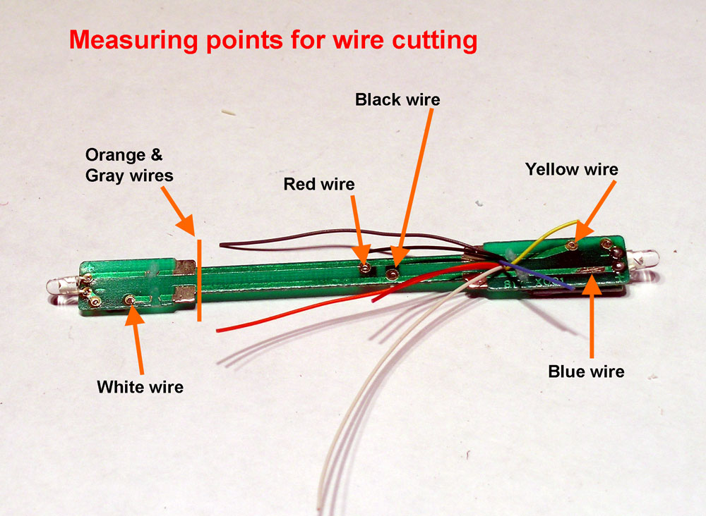
Cut the Train Control Systems Z2 decoder's wires to the following lengths:
 
Gray = 1-1/2 inch
Orange = 1-1/8 inch
All others = 1/2 inch


Strip 1/16 inch from the ends and then tin the ends of the Red, Black, Orange, and Gray wires. Remove the LED and resistor from the circuit board. Solder the red and black wires of the decoder to the points on the circuit board shown in this photo.

Then the decoder is attached to the PC board with a drop of Wathers Goo.  It is positioned so that it is in the spot where the LED was.  In this photo an original LED board is shown next to the board with a decoder mounted on it for comparison.  The decoder is longer than the LED but is narrow enough to fit between the frame.

The Goo will need 12 to 24 hours to set and it's best to use a clamp of some sort to hold the position.
Once the Goo has set, the decoder / PC board should look like the one in the bottom of this photo.  Remove the motor from the plastic saddle and then remove the brush contact clips.  Cut them down to the shape shown in the photo and solder the gray and orange wires to them.  Remember the orientation of the motor, the hole is towards the top.

With a jewelers file cut a groove down the left side of the motor just large enough to fit the orange wire into.

Then clip the orange wire to the top brush holder, and the gray wire to the bottom brush holder.


Lay the gray wire in the groove and wrap Kapton tape around the bottom of the motor so that it is covering the bottom brush holder and ends at the top of the motor on each side, which holds the gray wire in the groove.

Install the motor back in it's plastic saddle and then the frame can be re-assembled.  Plug the LED board into it original spot.  With a toothpick place a small amount of Goo between the motor and the plastic motor saddle on each side of the motor.  Let it get tacky then press the motor wires into that spot.

The short white, yellow, and blue wires can be secured the same way as shown in the photo or they can be just cut off.  I like to keep any unused wires on a decoder available in case they can be used in the future.  As an example, I have re-used several decoders  that had burned out motor outputs as lighting function decoders.

Almost done:

Check that the flywheel turns freely.  Then test the mechanism by attaching alligator clips between a DCC source and each side of the frame.  If that test good, then re-install the shell, the shims are not needed to re-install it.  Install the trucks and fuel tank, then test again on the track.  If that test good then re-install the weight and the cab and re-install the hand rails. 

Thursday, October 6, 2011

Add terminal strips to DCC Specialities PSX-1

OK, so this is not exactly a decoder install.  But I found that I really like these solid state DCC circuit breakers and figured anyone who was into DCC in any scale might benefit from this information.

This is a great little unit for setting up power districts on a larger layout.  It's a solid state circuit breaker that will trip when there is a short on the track and then clear itself when the short is cleared.  The basic hookup is real easy and there are also options on the board for the following:
  • Track power on remote LED
  • Track shorted remote LED,
  • Block occupied input
  • Block occupied remote LED
In my application I was installing 6 of these into a portable DCC power unit for a modular layout, that might be another post sometime.


The board comes with the green terminal strips on the ends for the DCC in and out but nothing for the other external connections I wanted to use.  I did not want to just solder the wires to the holes and the instruction sheet only says "Available from your dealer".


The spacing between the holes on the board for J4, J5, J6, J7, & J11 I thought was somewhat uncommon at 3.5mm but I was able to find a perfect fit.  Because all of the holes are in even numbers and the functions connections in pairs, I decided to use a 2 position terminal strip.  This type of terminal strip can be mechanically linked together to form a larger terminal strip as needed. 

I wanted to use the optional connections for track power ON and track shorted remote LEDs but the terminal strips I found will work for any of the external connections related to any of the optional functions.


Source:  Digi-key Corp.
              701 Brooks Ave. South
              P.O. Box 677
              Thief River Falls, MN 56701-0677
              http://www.digi-key.com/

Here is the information for the terminal strips.  It is actually cheaper to just get the 2 position ones and link them together as needed to make bigger terminal strips.

 Digi-Key Part #      Description                                                 Cost
281-1402-ND          Weidmuller 4-pos 3.5mm pitch terminal          1.89
281-1400-ND          Weidmuller 2-pos 3.5mm pitch terminal            .89

 Here is a link to the DCC Specialities instruction for the PSX-1:  http://dccspecialties.com/products/pdf/man_psx1.pdf

Friday, August 26, 2011

DZ121 in an Athearn F59PHI

This how to first appeared on my old web site in June of 2004.  Since that time the decoders mentioned have been replaced with newer models.  I would suggest the TCS M1 or Z2, or the Digitrax DZ125.  I don't think a board type decoder was ever made for this engine.

There is plenty of room for a small decoder without any modification to the frame. In this example I used
a Digitrax DZ121 but a DZ123, DZ143, or any similar sized decoder would also work.
The key to this installation is using the existing circuit board. The drawing of the board at the right shows all the steps taken to modify the board and then make all the connections to complete the installation.  Below are several photos to help clearly see what the installation should look like.

In this photo you can see where a section in the middle of the board has been removed for the decoder.  I used a Dermal tool with a cut off disk to do this.

After that the holes for the resistors get drilled & the circuit traces between the holes get cut. Then reverse the Led on the forward end of the board.

Next install a 270 ohm 1/4 watt resistor at each pair of holes. You will need to scrape away the green plating from around the holes before soldering.

An update to the way this was done in 2004 would be to change the yellow LED's to the bright white type of LED's. If this is done you may also want to change the 270 ohm resistors on the board to a higher value.

Note in the close-up to the left how the circuit trace has been cut between the points where the resistor is soldered.  This was also done with a Dermal tool and cut off disk.
 
These are the wire lengths that I use for this installation.

Black = 1-1/8"
Red = 1-1/16"
Orange = 15/16"
Gray = 1"
White = 1-3/8"
Yellow & Blue = 3/4"


Remove the motor brush mounts from the motor before soldering the orange and gray wires to them.

Then solder the white and yellow wires to the board at ends of the resistors that are away from the LED's as shown in the photo.

Cut the plastic bar that goes across the top of the wire channel on each side.  Reinstall the motor brush mounts with the orange wire going on the right side and the gray wire going on the left side.

Then solder the black wire to the tab on the bottom of the left side and the red wire to the tab on the right side.  Finish by tucking any excess wire length under the board and placing a piece of scotch tape over the decoder to hold it in place.


Monday, February 21, 2011

A most unusual shorted axle

Yesterday I had received an N scale Precision Craft E8A that I had installed a decoder in about 2 years before that now shorted the DCC system whenever it was put on the track.

The Precision Craft E8 is designed like a scaled down HO engine because it uses wires from the trucks, motor, and LED headlight that all plug into a circuit board.  The board also has an 8 pin connector that either has a decoder or jumper wires if it has no decoder.  I recalled that what I had done was to cut the jumpers on the original plug and then to solder the wires of a DZ125 decoder to the pins.

Here is a stock picture of a decoder like so you can get an idea of what this looks like.


This plug arrangement came in handy when troubleshooting this problem as I did not even have to turn on the soldering iron.  After first verifying that the locomotive indeed did cause a short of the DCC system as soon as it was on the track, I began to unplug things.
  • Unplugged the decoder, still got a short.
  • Unplugged the motor, still got a short.
  • Unplugged the rear truck, still got a short.
  • Unplugged the front truck, still got a short.
At this point, I placed each truck on the track one at a time and discovered that the front truck was the source of the short.  Because all three axles are picking up power and are connected on each side by a metal side frame I took the truck apart to test each axle and find the one that was shorted. 

First I checked the wheel gauge with an NMRA N scale standards gauge and it was OK.  Then pulling the wheels out from each side I could see that the pins that come off the wheels and insert into the plastic tube part were long enough for the ends to touch inside the plastic tube part.  I then took a bit off the end of one of the axle of one of the wheels  with a Dermal tool cutoff wheel and that solved this problem.


Almost all N scale locomotive axle assemblies look like the photo at left.  Two solid metal wheels with metal axle pins that insert into the ends of a plastic tube that has a gear.

It is easy to see how this could happen on any locomotive when the total length of the two metal axle pins are longer than the length of the plastic tube.

I would suspect that this could happen after someone pressed the wheels together to correct the wheel gauge.  The owner of this engine said it started after the engine had derailed.  I suspect that the ends of the 2 axle pins were already very close to touching and getting bumped by the derailment was just enough to make them short.  This ended up being one of those very unusual problems that I though was worth sharing.  I was relieved that the problem had nothing to do with my workmanship and the owner of the locomotive was relieved that the decoder was not burned out.

Sunday, February 6, 2011

Building a decoder tester


I have always found it useful to have a "simulated locomotive" with an actual motor to test decoders.  Back when I started working with DCC, I threw something together from the junk box and ended up using that for many years.

In 2010 that one finally fell apart and I set out to make a nicer one and here it is.


Here's a peek inside.   To keep things simple I mounted all of the components on the top half of the two part plastic project box.  The size of the box is 5-1/2" x 3" x 1-1/2".


The cord that comes out of the box has a Cinch Jones connector on it that I can plug into these two receptacles on my layout control panel.  The layout uses a Digitrax Chief System.

I also have an old Digitrax Big Boy system mounted on a board that I use on the work bench and this decoder tester can also be plugged into that.


Here's a drawing and a parts list along with where I found them.

Besides marking the color for the binding posts, the banana plug sockets are for any special leads needed to connect to board type decoders.


  1. The nickel plated binding posts are Grayhill 29-100 BLK which I purchase from Allied Electronics.  Their part number is 948-7392.  At $4.79 each, this was the most expensive part of the project.
  2. E-Z Hook 9284-5R is a set of banana plug jacks that I found at Fry's Electronics for about $6.00.  The Fry's part number is 18206.  The full set had 10 jacks with colors matching the wires on a decoder.  I did not use the violet or brown ones but if you are working with HO scale decoders that would be something to consider.
  3. Motor assembly from Kato E8 or PA locomotive.  I used this one because the mount was easy to attach to the inside of the box with Walthers Goo.  A striped pattern was printed on adhesive labels and attached to the flywheels to the motors rotation would be easy to view through the windows.
  4. Three yellow LED's taken from Atlas locomotives when they were upgraded to bright white LED's.  One each for the white, yellow, and green (F1).